
HYDROPONIC SYSTEMS · SPECIFIED ROCUM
Aeroponics
Nutrient solution sputter in a controlled manner, uniformly wet free roots and control precipitation.
ORIENTATION
Content
- 01Definition and classification
- 02Types: low pressure, high pressure and delimitation
- 03This is how aeroponics works – the complete material flow
- 04Components and their actual task
- 05Drops, wetting and root contact
- 06Pump, pressure and real operating point
- 07Nozzle arrangement and distribution test
- 08root zone, oxygen and reflux
- 09Reservoir, filtration and nutrient solution
- 10pH, EC, temperature and oxygen
- 11Spray cycle and cycle without blank values
- 12Installation and commissioning
- 13Appropriate cultures and boundaries
- 14Operation, maintenance and cleaning
- 15Incidents, alerts and emergency services
- 16Hygiene and food safety
- 17System comparison and scaling
- 18Planning checklist and specialist sources
01Definition and classification
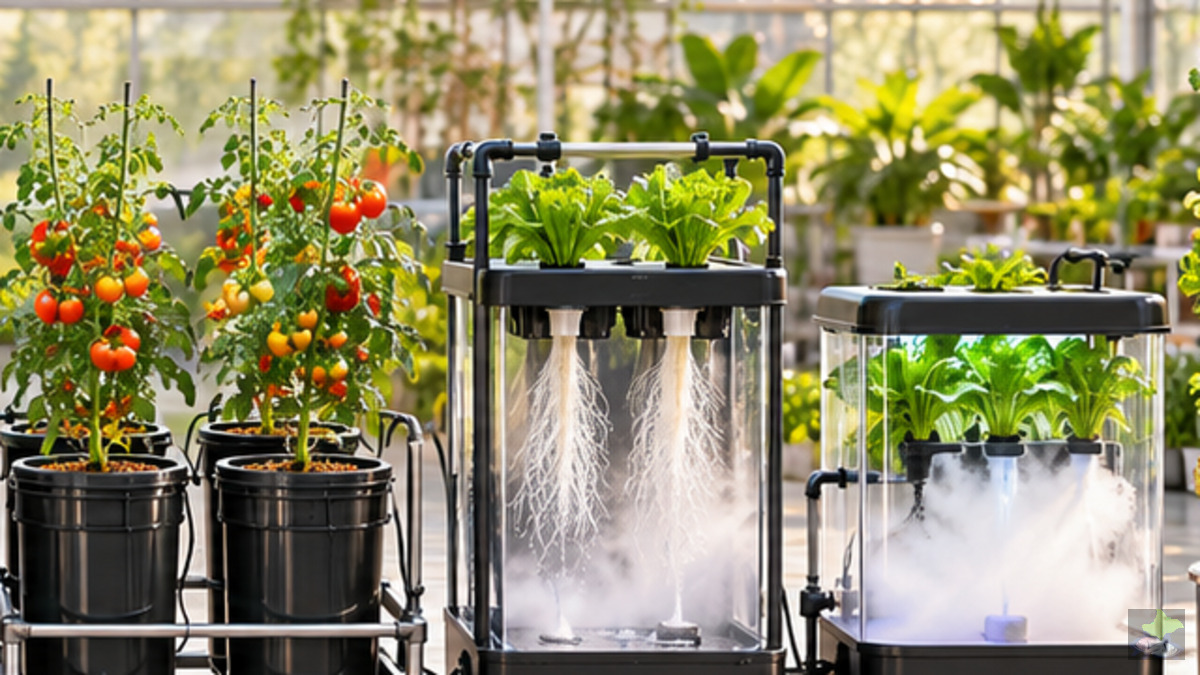
Aeroponics is a substrateless culture form in which the plants are kept above a closed, light-tight root zone. The roots hang predominantly freely in the air-filled interior and are wetted with nutrient solution in recurring spray phases. Between the drops, a large part of the root surface remains in direct contact with the chamber air.
The system therefore consists not only of “a pump and a few mist nozzles”. It connects a hydraulic pressure circuit with a pressureless return, a biologically active root zone and a time-dependent control. If only one of these subsystems fails, the supply can be disturbed within a short time.
02Types: low pressure, high pressure and delimitation
In low-pressure aeroponics, conventional pumps promote nutrient solution to relatively large spray openings. The spray pattern is coarser, the nozzles are usually more tolerant of small particles, and the construction can be simpler. Nevertheless, the solution must reach all root areas; “Low pressure” is no excuse for uneven distribution.
High-pressure aeroponics works with a coordinated chain of pressure pump, suitable pressure accumulator, fine filter, valve and nozzles. It can produce finer and more reproducible spray images, but requires more maintenance and measurement. Fogponics generates aerosol using ultrasound and is therefore not treated as a mere HPA variant.
Differentiate low pressure, high pressure and fogponics
- Larger nozzles, simpler hydraulics
- Pressure pump, fine filter, reservoir
- No nozzle spraying system; own specialist site
- LPA
- Low-pressure aeroponics with coarser spray pattern
- HPA
- High pressure aeroponics with pressure accumulator and finer nozzles
- Fogponics
- ultrasonic aerosol; Not synonymous with HPA
03This is how aeroponics works – the complete material flow
The circulation begins in the light-tight reservoir. An intake filter protects the pump from coarse particles. The pump raises the pressure level; With HPA, a pressure accumulator designed for this stabilizes the pressure side. A fine filter protects the small nozzle openings, while a manometer makes visible the actual pressure available.
When the solenoid valve opens, the solution flows to the nozzle strip. Each nozzle forms a spray cone. The droplets meet the freely suspended fine roots, form a liquid film there for a short time and provide water and dissolved ions. Unabsorbed solution falls down and runs back into the tank by gravity.
During the spray pause, the chamber remains predominantly air-filled. Exactly this interplay of wetting, air contact and safe operation is the functional principle. Standing water in the chamber floor, dry shadow zones or a flooded root neck contradict this principle.
Overall cross section: This is how an aeroponic system works
- Blue
- Nutrient solution on the pressure side
- Light blue dashed
- Spray cone and drip flight
- Brown
- Free-hanging roots
- Green
- pressureless return
- 1–6
- Order of a complete circulation
04Components and their actual task
Each component performs an independent supply or protection function. The plant is only as reliable as its most difficult-to-access filter, its least favourable nozzle and its narrowest return. Maintenance access is therefore planned before assembly.
Light-tight reservoir
Store and mix the nutrient solution; absorbs the entire return without allowing the suction to drop dry.
Intake filter
Retains coarse particles in front of the pump and must be controllable without emptying the system.
Pump pump
Provides the necessary volume flow at the pressure that is still available at the nozzles after all line and filter losses.
Pressure storage device
Calms pressure fluctuations and reduces frequent pump cycles with suitable HPA concepts; It does not replace a suitable pump.
Fine filter and pressure gauge
Protects nozzle openings and makes pressure loss visible. Without a measuring point, a creeping filter error remains hidden.
Magnetic valve/control
Opens the spray phase reproducibly. Control and valve need a defined safe state in the event of power failure.
nozzle bar
Distributes the total flow over several spray cones. Arrangement, angle and accessibility determine uniformity and maintainability.
root zone and return
Keeps light away, provides air volume and returns surplus to the reservoir without puddles or root jams.
05Drops, wetting and root contact
A nozzle does not create an evenly filled “mist space”, but a spatial drop pattern. Drop size, speed and range depend on nozzle, pressure, solution properties and wear. Roots and holders increasingly shaded parts of the spray cone.
The technical test therefore not only asks whether a nozzle sprays visibly. The decisive factor is whether comparable quantities arrive at several positions in the same time, the root crown does not become permanently wet and sufficient free air remains between the wettings.
Spray cone, overlap and catch test
- Collection cup at several positions
- Compare volumes in the same time
- Detecting dry spots and partial blockages
- Spray cone
- spatial area of a nozzle
- Overlapping
- Root shadow reserve
- Collection test
- Same measurement time, compare volumes per position
06Pump, pressure and real operating point
The delivery information on the pump housing does not describe a guaranteed state at the nozzles. Filters, line length, cross section, height difference, arcs, valves and the total number of nozzles generate pressure losses. At the same time, each additional or partially blocked nozzle changes the total flow.
This is why pressure and volume flow are tested together on the finished system: pressure gauge near the distribution line, time-related volume measurement and documented filter status. Only this operating point shows whether the selected nozzles operate in the intended area.
Pump characteristic and real operating point
- Manometer at the distributor
- Measure total flow time-related
- Filter status with documented
- Pump characteristic curve
- What the pump can deliver at pressure and flow
- System curve
- Resistance of line, filters, valves and nozzles
- Operating point
- actual measured intersection point
07Nozzle arrangement and distribution test
Nozzles are arranged so that their spray cones overlap the active root zone. A mere symmetrical assembly does not guarantee a uniform supply, because line lengths, pressure drop and growing roots change the distribution.
For the collection test, similar measuring vessels are placed at representative positions. After exactly the same spray time, the volumes are compared. Significant deviations lead to inspection of nozzle, angle, line, pressure and partial blockage – not immediately to longer spray times for the entire system.
08root zone, oxygen and reflux
The plant holder carries the shoot and starter substrate, but is not a permanent root container. New roots grow into the chamber. The root crown remains above the strongest wetting, while fine roots lie in the spray area. Free airspace provides oxygen.
The chamber bottom is given a slope and a sufficiently large, root-protected drain. If solution remains, the plant locally approaches a poorly ventilated deep water culture. If the reflux increases, moisture, oxygen and hygiene change simultaneously.
root zone: crown, fine roots, air and drain
- above: Mechanically carrying a plant
- middle: air and drops at the same time
- below: no standing water
- Crown
- transitional shoot/root; Not permanently flooded
- Fine roots
- repeatedly wetting active receiving surface
- Airspace
- Oxygen supply between drops
- Expiry date
- Excess without backlog
09Reservoir, filtration and nutrient solution
The reservoir shall be capable of absorbing the minimum operational volume, variations due to plant uptake and complete return. Intake and return are separated in such a way that no air is sucked in and no sediment is carried directly back to the pump.
The filter chain is laid backwards from the smallest opening in need of protection. An accessible coarse filter protects the pump; a defined fine filter protects the nozzles. Organic additives, poorly dissolved salts and biofilm increase the risk of blockage and require their own compatibility test.
10pH, EC, temperature and oxygen
pH affects the chemical availability of nutrients; EC shows the conductivity of the dissolved ions, but not their balanced composition. Temperature changes plant consumption, reaction rate and oxygen solubility. Dissolved oxygen in the reservoir does not automatically replace air contact in the chamber.
A single value therefore does not prove a secure supply. Level, water level, refill quantity, nutrient addition, temperature, pressure, spray pattern, leaf position and root color are evaluated together.
11Spray cycle and cycle without blank values
A spray phase must deposit enough solution on the active root surface. The break may be long enough for air contact, but not so long that the roots dry out critically. There is no universal second sequence, which applies independently of nozzle, climate, root mass and culture.
The setting starts conservatively and is refined via root observation, reflux and plant reaction. In addition, an alarm window is set: an independent emergency wetting system starts at the latest before its end or the culture is manually secured.
Spray phase, pause and alarm window
- Set duration on the real system
- Observe residual humidity and climate
- Testing border practically and safely
- Spray phase
- Drops reach the root surface
- Pause
- No pump running; root zone remains airy
- Alarm window
- Time for safe emergency response, no universal number
12Installation and commissioning
- Clean and rinse the reservoir, chamber and lines.
- Check for tightness and free reflux with water.
- Use filters; Pump briefly vent and control suction.
- Measure pressure at the distributor and total volume flow.
- Perform interception tests at upper, middle, lower and near-edge positions.
- Test control, solenoid valve, alarm and emergency wetting.
- Use young plants, protect root crowns and slowly adjust timing.
13Appropriate cultures and boundaries
Leaf vegetables, herbs, young plants and vegetative propagation can be well suited if root zone and spray distribution fit. Research systems also use aeroponics because roots remain accessible and observable.
Large fruit plants, long culture periods and highly branched root systems increase requirements for supporting structure, chamber height, nozzle maintenance and return. Potato miniatures are a documented special case; Results of a test set-up shall not be transferred across the board to other crops.
14Operation, maintenance and cleaning
Every day, pump noise, pressure gauge, spray pattern, return, leakage and plant keeping are checked. Several times a week, filter status, total flow, pH, EC, temperature and water consumption are documented as a course.
For cleaning, sections are isolated. Detached deposits leave the plant via a flushing connection and are not pressed through sensitive nozzles. After each procedure, a new collection test is carried out.
Filter, rinse and cleaning route
- Accessible in front of the pump
- Document differential pressure/condition
- Do not rinse back through nozzles
- Intake filter
- Protects pump from coarse particles
- Fine filters
- protects small nozzle openings
- Washing distance
- carries detached deposits from the system
15Incidents, alerts and emergency services
In the case of wilting or dry root tips, the supply is first ensured. This is followed by the diagnosis from common to local error: power supply, control, pump, suction, main filter, valve, distribution line and individual nozzles.
If all plants are affected, the cause is probably in the common path. If the symptom affects only one zone, local line, nozzle, spray shadow and drain are examined. Increasing fertilizer or spray time without root cause testing can exacerbate the problem.
From symptom to testable cause
- Do not fertilize immediately
- from common to local error
- Retest distribution after repair
- Common error
- all nozzles affected: electricity, pump, main filter
- Local error
- an area affected: line or nozzle
- Emergency wetting
- Protect roots while fixing the cause
16Hygiene and food safety
All materials in contact with the chemical(s) being processed must be suitable for water, nutrient salts, cleaning products and the intended food context. Access to light, dead spaces, rough interior surfaces and standing backflow promote deposits and biological deposits.
Root remains are removed before they reach drain and filters. Cleaning and disinfection steps are selected so that no incompatible residues enter the plant cycle.
17System comparison and scaling
As the plant grows, not only pump output and number of nozzles increase. There is also an increase in the number of defects, cleaning effort, spare parts requirements and the number of plants at risk at the same time. Scaling requires hydraulic zones and sectional maintainability.
18Planning checklist and specialist sources
ESTABLISHMENTS AND DELIVERY
Specialist and primary sources
The sources are classified according to their technical task. Under each link it says which statement of the page is proven or deepened.
-
01NASA technology demonstrationNASA: eXposed Root On-Orbit Test System (XROOTS)
Technology demonstration for deep-rooted fluid delivery and recovery in microgravity. The source supports the separation of root zone, fluid guidance, observation and operational protocol.
-
02NASA system descriptionA Novel Approach to Growing Gardens in Space
Explains the structure, test objectives and different operating methods of the XROOTS system. Relevant for system architecture, root observation and controlled testing of spray and liquid distribution.
-
03USDA definitionUSDA National Agricultural Library: Aeroponics
Official definition of aeroponics as a substrateless process in which exposed roots are intermittently or continuously wetted with a fine nutrient solution.
-
04USDA root researchUSDA Agricultural Research Service: Aeroponic examination of root systems
Describes an aeroponic root zone for observation and sampling. The source proves the research benefits of an accessible, predominantly free-hanging root zone.
-
05USDA nozzle studyUSDA Agricultural Research Service: nozzle type and spray direction
Compares nozzle and spray direction variants in an aeroponic potato culture. It shows that nozzle selection, antidrop function and alignment influence the specific structure and must be tested.
-
06USDA Root StudyUSDA Agricultural Research Service: pH and Root Architecture
Investigates the influence of different pH conditions on the formation of the root system. The source supports the joint evaluation of solution chemistry, root image and plant reaction.
-
07Basic University SourceOklahoma State University Extension: Hydroponics
Organizes aeroponics within hydroponic processes and describes free-hanging roots in a closed chamber with recurring spraying.
-
08NASA technical reportNASA Technical Memorandum: Terrestrial Agriculture Applications
Early technical consideration of hydroponic and aeroponic growth spaces. It serves as a historical system basis, not as a directly transferable construction or dimensioning guide.
Editorial note: Results from microgravity, woody or potato tests are used exclusively for the proven technical statement. Pressure, nozzle selection, timing and nutrient solution must be tested for culture, climate and specific plant design.