
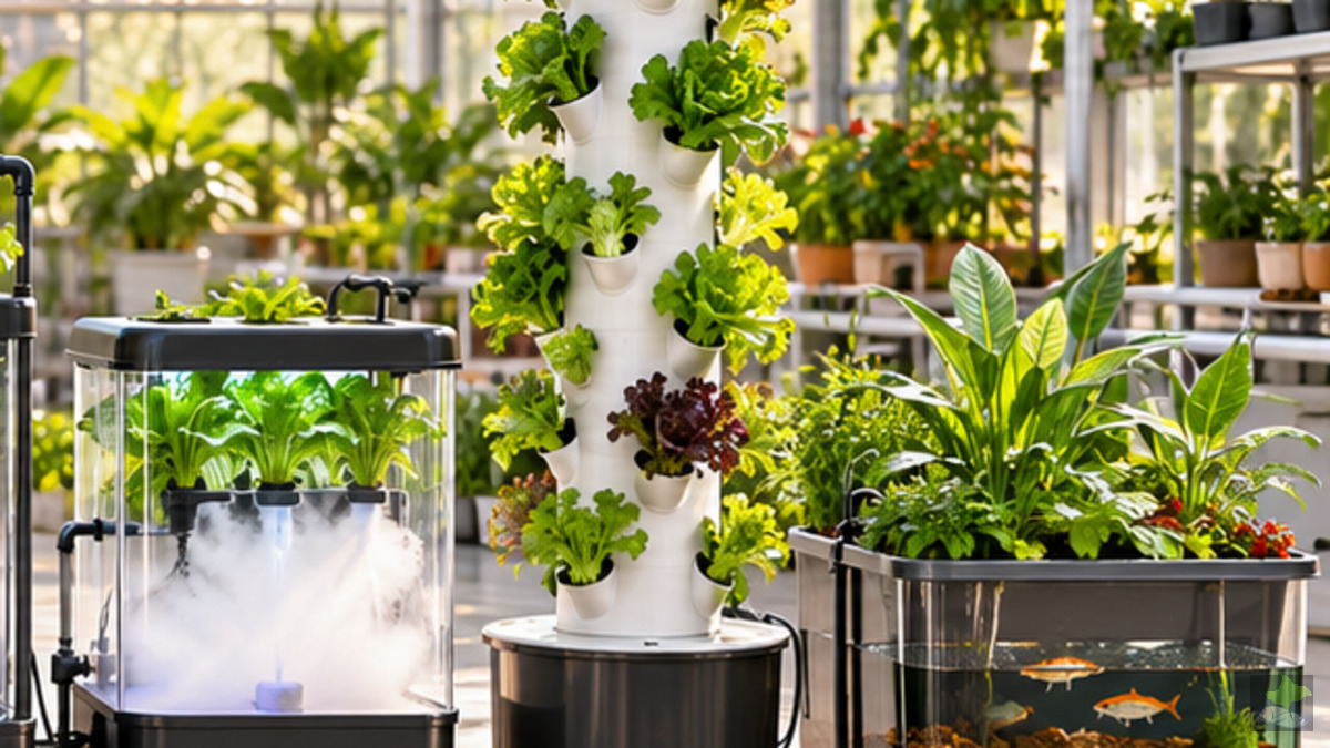
HYDROPONIC SYSTEMS · VERTICAL RECIRCULATION SYSTEM
Hydroponic planting tower
Content
- 01Definition and classification
- 02Vertical hydroponic tower construction types
- 03Functional principle and source stream
- 04Components and their actual task
- 05Head and pump design
- 06Distribution at tower head
- 07Tower geometry and root zone
- 08Wetting, oxygen and drying
- 09Reservoir, reflux and filtration
- 10Nutrient solution and water quality
- 11Lighting, shading and stock management
- 12Suitable crops and planting distances
- 13Installation and commissioning
- 14Operational routine and cleaning
- 15Defect diagnosis: Symptom → Examination → Measure
- 16Hygiene, materials and food safety
- 17System comparison, limits and scaling
- 18Planning checklist and specialist sources
A planting tower is not just an erect NFT channel. Conveying height, top distributor, falling solution film, root zone and free return form their own hydraulic chain.
Definition and classification
A hydroponic planting tower arranges planting sites on top of one another around a vertical supply body. A pump raises nutrient solution upwards; Gravity leads them back past the roots.
The term describes the geometry, not automatically a specific watering process. Depending on the design, the solution flows, drips or sprays within the tower.
The drip tower, vertical NFT module and aeroponic tower differ in root contact, drop size, oxygen access and failure risk.
Vertical hydroponic tower construction types
Under the name “Hydroponic Tower” technically very different systems are sold. For planning and operation, it must first be clarified how the roots actually come into contact with nutrient solution.
Solution emerges at the top and runs down on the inner wall, guide webs or root surfaces. The root zone remains predominantly air-filled.
Each planting site contains a larger substrate volume. droppers or internal distributors moisten the modules; Moisture buffers and salt deposits are becoming more important.
Nozzles produce drops or fog in the closed root zone. This is functional aeroponics and places higher demands on filtration, pressure and failure protection.
| Characteristic | Inner film | Substrate/drop | Spraying/Aeroponics |
|---|---|---|---|
| Water buffer at the root | Small | Medium to high | Very low |
| Blockage risk | Distributor/root felt | Dropper/substrate | Nozzle/filter |
| Failure tolerance | Design-dependent | Higher by moisture buffer | Usually low |
| Cleaning centre | Inner channel and head | Modules and substrate | Nozzles and pressure line |
Functional principle and source stream
Overall cross section: This is how a hydroponic tower works
The immersion pump removes nutrient solution in the reservoir. A filter holds particles back before they reach the line and distributor.
The riser ends in the tower head. There, the total flow is divided into a plurality of partial flows which are as equal as possible.
The solution proceeds as a film or in drops at guide elements and roots. The rest of the interior remains air-filled.
The partial streams combine at the tower foot. A sufficiently large, root-proof outlet leads them back.
The reflux and residual volume mix in the reservoir. The cycle then begins again.
A tower is not a pillar full of water. The solution is pumped up only; Downwards, gravity works. Therefore, the rise side and the fall side must be designed separately.
Components and their actual task
Each component performs a hydraulic, biological or safety-relevant task. “Some pump and pipe” do not yet produce a resilient culture system.
Light-tight collecting and mixing container. It must be capable of absorbing residual volume, circulation volume and return after pump stop.
Protects pump and small distributor openings from root pieces, substrate and deposits. It shall be accessible without dismantling the tower.
Delivers the required volume flow at the real operating point – i.e. at the actual delivery head and all line losses.
Transport the solution to the head. Diameter, length, arcs, valves and cross-sectional constrictions change the available flow.
Converts a feed into several partial streams. It shall be horizontal, inspectable, removable and cleanable.
Carries the planting sites, protects roots from light, keeps air in the root zone and guides the solution down.
Fixes young plant and starter substrate. The later root volume is predominantly outside the small insert.
Bring back the unified film without a backlog. Maintenance opening and root protection are more important than a visually small design.
In modified designs, Oklahoma State explicitly refers to food-compatible materials, a light-tight tank, corrosion protection and a mechanical securing of the tower.
Head and pump design
Pump design at real operating point
- Measure vertical distance between lowest operational water level and highest outlet.
- Line length, internal diameter, arcs, valves, filters and distributors.
- Derive the total flow required from the number and minimum flow of the outlets – then provide reserve for pollution.
- In the manufacturer's characteristic curve, check which delivery volume actually remains at this total delivery head.
- Measure at the finished tower: total current and partial currents. A valve can throttle oversupply; Undersupply requires a different interpretation.
The most common misinterpretation is the zero-height flow mentioned on the packaging. This value does not describe what arrives at the top of the Tower.
Distribution at tower head
Distribution head: uniformly divide an inlet
Constructive requirements
- symmetrical paths or hydraulically balanced outlets
- Horizontal mounting without hidden high points
- Removable cover and mechanically accessible openings
- no uncontrolled wetting of leaves and root neck
Test before planting
- Subordinate all vessels simultaneously
- Select identical measurement duration
- Log volumes and assess spread
- Test after filter cleaning and later repeat under root load
Tower geometry and root zone
More planting sites per meter do not automatically increase the usable production output.
Leaves need light, air movement and distance to the next crown.
Roots must not block neighboring places, returns and cleaning access.
The OSU guide describes 28 places per concrete example tower. This figure documents this design – it is not a universal stocking recommendation.
Wetting, oxygen and drying
Planting site in cut: film, root and air
The film does not reach the planting site, is deflected from upper roots or tears off too long during pump cycles.
Roots are repeatedly wetted without being completely under water. Air can circulate between the root strands.
Root felt, oblique tower or narrow drain jam solution. Died roots and biofilm exacerbate oxygen deficiency.
The waterway changes during the culture. An empty tower can run evenly, while the same distributor generates completely different paths several weeks later by root mass. Therefore, visual inspection of each elevation zone is part of the operation.
Reservoir, reflux and filtration
Reservoir, circulating volume and safe return
With pump running
The pump must remain fully immersed. The tank level must not drop to such an extent that air is sucked in or the solution is greatly heated.
After pump stop
The riser and tower empty partly. This volume must be accommodated in the reservoir without overflowing lids, cable bushings or maintenance openings.
A visible return point immediately provides indications of pump performance, blockages and delays. Hidden lines require an inspection opening for this.
Nutrient solution and water quality
Water level, EC, pH, culture stage and starting water are assessed together.
Lighting, shading and stock management
Light and stock geometry
USDA ARS cites light and air conditioning as central limits of vertical production. Compact, short-cyclic leaf cultures usually fit better than large fruit cultures.
Suitable crops and planting distances
Salads, compact herbs and smaller leaf cultures.
Strawberries and compact fruit crops: observe light, support and pollination.
Large, heavy or deep-rooted crops with high individual plant requirements.
Installation and commissioning
- 01Prepare the location horizontally and securely
- 02Set up tank light-tight and overflow-proof
- 03mechanically securing tower
- 04Test the reflux dry for free cross section
- 05Pump, hose, filter and valve assembly
- 06Rinse with water and look for leaks
- 07Measure distribution at all outlets
- 08Prepare nutrient solution and document values
- 09Only then use young plants
Operational routine and cleaning
Pump noise, top distribution, wilting, leakage, return and tank level.
pH/EC profile, check all tower sides, filter and root growth.
Decalcify distributors, limit roots, clean tanks and pipes.
Defect diagnosis: Symptom → Examination → Measure
Diagnostic pathway for uneven care
Hygiene, materials and food safety
Contact surfaces
Use food-appropriate cleanable materials. Avoid inaccessible cavities.
Process hygiene
Remove dead roots, biofilm and sediments; Rinse cleaners completely.
System comparison, limits and scaling
Vertical land use is the profit. Hydraulic dependency, shading and maintenance access are the price.
Direct system comparison
Planning checklist and specialist sources
Release before construction
Specialist sources used
- Oklahoma State University Extension: Building a Vertical Hydroponic TowerDocumented example construction and material instructions
- USDA Agricultural Research Service: Vertical FarmingCulture choice and light, climate and energy limits
- USDA National Agricultural Library: HydroponicsDefinition and government research resources
- University of New Hampshire Extension: Hydroponics at HomeNutrient solution management and state-dependent solution change
- University of Nevada, Reno: Hydroponics – A Brief GuideOpen and closed systems and location basics
- Virginia Cooperative Extension: Hydroponic Media SystemsSubstrate function, pot watering and system delimitation
Editorial note: Example values are not output as universal system values. Dimensioning takes place on the concrete tower, the culture and the measured operating state.